USABILITY TESTING:
PAPER PROTOTYPE
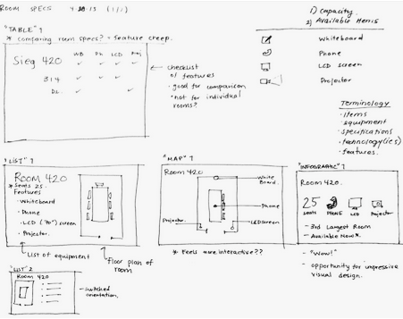
- We built a paper prototype by printing our wireframe UI layouts and placing them into transparent page protectors. Because our screen flow is mostly linear, and few elements change on the individual screens as users interact we were able to switch pages and users interacted with our paper prototype of our UI once we’d established that the screen would have touch capabilities. We designed the prototype with global navigation of buttons at the end – to allow the user to select which screen/information they wanted to view. We created two scenarios that would address the previously mentioned task list (this list be found in milestone 2).

- Our objectives in completing these usability tests were to:
- See how users interact with our system.
- Understand their first impressions of screens / iconography
- Look for points that are confusing or are unclear to the user.
- From our usability tests we wanted to identify areas where the UI can be improved, and gain an understanding of users interpretations of the design and interactions. We executed our guerilla style usability test on students near one of the libraries on campus.
USABILITY TEST:
- We performed our tests on students near the Allen research commons. We asked them to imagine they were in certain scenarios and interact with our prototype to accomplish the tasks we read to them. Two of our teammates conducted the tests – one handled the prototype and made the necessary screen changes as the users interacted with the device. The other read the scenarios and took notes about the user’s reactions and interactions. The tests were the same for every user.
- FINDINGS:
- Positive:
- A user liked that they “could see on the device other free rooms versus having to hunt through the building.”
- “Flow through screens made sense.”
- Negative:
- A user was confused on which elements were clickable, and questioned “can I click on that?” before interacting with the screen.
- A user mentioned “it may have been useful to view the current room’s equipment from the main/default page.”
- “Iconography for room equipment was confusing.”
- User’s unanimously prefer the grid/table design for the screen that provides other room information.
- Positive:
IDEATION:
- From our usability tests we analyzed the additional feedback we got from users and from there decided which of the feedback we’d apply to improve the final UI design. Our significant UI change came from implementing the preferred view of the “other rooms screen”. In addition we added additional information like the QR code & phone number to aid users ability to make on-the-go reservations. After these changes were made in our wireframes, we began to implement the UI design on the device!

DEVELOPMENT:
NOOK:
- The nook was selected to be our primary display due to its low-cost and also its energy efficiency as an e-paper display. In order to build our interface on this platform, the Nook was rooted to its native Android 2.1 firmware. The actual interface itself was build using web programming languages (HTML, CSS, and Javascript). However, it was encapsulated within an Android app through a component called the Android WebView. While building this interface, a number of JavaScript tools were used that helped speed up the development process. The first one was the jquery-week-calendar plugin created by Rob Monie. This plugin helped establish the groundwork for the weekly calendar view which we then modified. The other equally important tool was the aREST API created by Marco Schwartz. This API was vital in connecting the Nook to the Arduino and sending it requests to turn on and off the LED lights indicating room status.
ARDUINO + CC000 WiFi Breakout Board

- The Arduino was selected to control the LEDs that indicate the status of a room from a distance (Green for an available room, and red for an occupied one). The CC3000 WiFi Breakout Board was used to communicate with our web app and read room availability status changes.
ENCASEMENT:

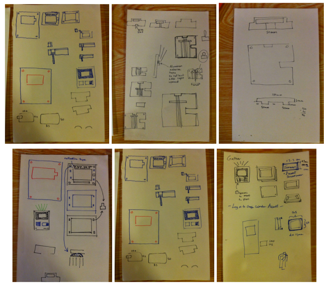
- We started designing the case by sketching various possible configurations. After settling on a final design, we began to create 2d models in Adobe Illustrator which were used to make laser cuts. first in cardboard to get a feel for the fit of the pieces, and then in acrylic for a more durable and aesthetically pleasing encasement.

- The illustrator files are formatted in millimeters and color-coded specifically for laser cutting, with black lines indicating cuts and red lines indicating rasterization (i.e., pixelated cuts that resulted in deep grooves but did not go all the way through the material). the rasterized sections were to ensure that our material didn’t activate any of the buttons on the Nook, created indented surfaces for gluing and embedding nuts and bolts, and served as channel guides for wiring.

- We started with some basic laser cuts in cardboard to gauge the fit of the pieces and evaluate the orientation of our components for aesthetic value.
- The purpose of the laser cut plexiglass
- To showcase our hardware and “diy/hacked” style.
- Encase and protect our delicate hardware.
- To match the aesthetics of the department hallway decor.
- The purpose of the laser cut plexiglass

- The encasement and layout of the hardware felt right, so we made our final cuts, and began working on the wiring. We prototype the circuits first, cut our wires, and started soldering.

- Every last detail of the encasement was thought out–from the smoky black frame which allowed the profile of the Nook to remain visible, to the choice of wire and breadboard colors which tied the black, white, and blue theme of the device together. Things like the way the Nook was locked in all the way to the choice of bolt lengths were chosen to make parts difficult to tamper with.
Our final design presented on our poster at our Capstone Open House!
Presenting availa [board] a system that provides users with up-to-date information and indicates the status of a meeting room from a distance!